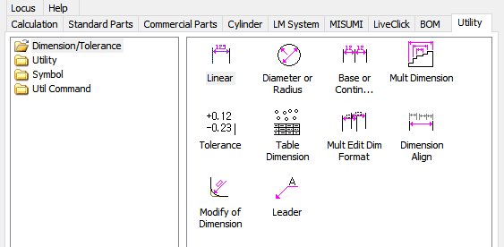
2017년 1월 25일 수요일

4-3 Leader : Create object information

Leader ?
 Unlike the normal 'leader', it takes the information of the object and automatically creates the character without typing.


A. 'Leader' Location
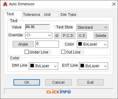


B. Interface Window


  1) Note : You can register frequently used boilerplate by clicking the 'Save input character' button or delete it with 'Delete selected item'. You can specify the height, color, type, and border of the characters.


2) Attachment: You can set the attachment position of text and apply existing dimension style value.


C. Usage example
 Create a leader using MechClick's 'Counterboring' library feature.


4-2 Modify Of Dimension : Real-time changes

Modify Of Dimension?
 If you modify the dimension value using the Change Dimension value, you can also modify the size of the object associated with the dimension


A. 'Modify Of Dimension' Location


B. How to use
 Select the created dimension, enter the change value, and execute it.


4-1 Diameter Or Radius

Diameter Or Radius?
 If you select objects related to diameter and radius, you can automatically fill in the dimensions you want. In addition, you can freely select and apply the dimensioning method within the option setting.


A. 'Diameter Or Radius' Location


B. How to use


3-3 Table Dimension

Table Dimension ?
 The table automatically creates the X coordinate value, the Y coordinate value, and the size of the circle around the base point specified for the circle.


A. 'Table Dimension' Location


B. Interface window


You can specify reference point, coordinate character, table option and convert to Excel.


C. Usage example
 You can create a table with just the base point and circle selection, but you can also set the creation order, coordinate number, and text height in the interface window.


3-2 Multi Dimension : Real-time editing

Multi Dimension?
 You can select multiple objects to create multiple dimensions simultaneously with the desired dimension type.
 Even if you have finished dimensioning, you can select the dimension and rerun the options window.


A. 'Multi Dimension' Location


B. Interface Window
 There are continuous dimension, standard dimension, parallel dimension, coordinate dimension, diameter dimension and radius dimension type.


C. Usage example
 Select the object after executing 'Multiple dimensions'. Then select the Run button twice and the option window will be created. If you have already made it, you can edit it again.


3-1 Base of continue dimension

Base of continue dimension ?
 You can change continuous and standard dimensions in real time based on the selected dimension. For continuous dimensions, you can also specify an interval.


A. 'Base of continue dimension' Location


B. How to use
 Immediately after execution, you can right-click and specify options. The biggest feature is that you can change the type in real time and fill in the dimensions easily.


2-4 Tolerance : Generated dimensions

Tolerance ?
It is the function that gives the tolerance value by selecting the already written dimension. In case of fitting tolerance, there is an advantage that the tolerance value is automatically changed according to the object length. (Based on the data table)


A. 'Tolerance ' Location


B. How to use
 After setting the tolerance value, you can apply the tolerance value by clicking on the created dimension.


2-3 Edit Multi Dimension : Generated dimensions

Edit Multi Dimension?
 Options such as text editing, alignment, tolerance, dimension line suppression, and arrow change can be applied to created dimensions.


A. 'Edit Multi Dimension' Location


B. How to use
  
1) Geometry: You can change dimension line, arrow size, slope, color and so on.


2) Alignment: You can set options for dimension line position, dimension text, and alignment.


3) Text: You can set the size of text, style, and sort of dimension text.


4) Unit: You can set the accuracy of all dimensions already created.


5) Tolerance: Tolerance can be applied.


2017년 1월 24일 화요일

2-2 Dimension Align

Dimension Align?
 The dimension line alignment feature offers a variety of alignment types to help you avoid manual manipulation due to dimensions.


A. 'Dimension Align' Location


B. Learn about options


C. How to use
 First click the basic dimension, then select the dimension you want to apply and run it. You can set the dimension line spacing.


2-1 Linear : Automatic dimension position adjustment

Linear ?
 Applies vertical, horizontal, and alignment types automatically based on line type. It is related to the function of 'MechClick'.


A. 'Linear' Location


B. How to use
 The dimension type is automatically applied according to the type of line.


You can use the shortcut keys to pin the type you need.

1-1 Dimension Option : Right mouse click

Dimension Option?
 Dimensioning function of 'MechClick' provides optional function. When the right mouse button is clicked, an option window is displayed, and the character function, tolerance function, precision unit setting, and dimension type to be written as dimensions are provided. Each dimension function has a different dimension type.


A. Dimension Option
 You can activate the dimension options window by right-clicking on it before defining the dimension function fully.


1) Characters: Attached characters can be specified at the time of dimension writing. In
                     addition, options such as font and color can be specified.


2) Tolerance: fit tolerance, general tolerance can be applied.
   

3) Unit: You can specify the precision of the dimension and can suppress 0.
            (0.5 > .5 / 1.50 > 1.5)


4) Dimension type: There is different type for each dimension, and you can also specify the
                            dimension layer.


B. How to use
 You can activate the dimension options window by right-clicking on it before defining the dimension function fully.


4-1 Export Part List : Text File, Excel File

Export Part List 
 Export Parts Use the list to export the BOM created in the drawing to an EXCEL file. You can specify Excel's rows and cells directly.


A. 'Export Part List' Locate


 B. 'Export Part List' Interface


 a. Drawing area name: You can select the drawing area to be documented.
 b. Work sheet name: Enter the sheet name of the Excel work sheet.
 c. Document start cell (row): Enter the start cell (row) where the bill of materials will start.
 d. Save Location: Select the Excel file to save.
 e. Title display: Select whether to display the title when converting.
 f. Bill of materials specification: You can specify the position of the cell when exporting Excel.


 C. Using 'Export Part List'
If you specify the cell and row location according to the purchase order form, you can complete the purchase order without any additional work.

(You can set it in the BOM Table spec option.)


<Reference>


3-4 Convert Part List : Use Existing Parts List

Convert Part List?
 You can convert the previously created table to use all editing functions of 'MechClick' by applying the 'Part conversion table' function. 


A. 'Convert Part List' Locate


B. How to use 'Convert Part List' 1


 a. First point: Select the bottom left corner except for the title.
 b. Second point: Select the upper right corner, which is the last part of the BOM.
 c. Third point: Select the point directly above the first point to set the row height of the bill
                      of materials.


 C. How to use 'Convert Part List' 2

      
(Change the column according to the title order of the existing parts list.)


  DHow to use 'Convert Part List' 3

(The converted content can also be entered as part number.)